Automatic Temperature Controlled Fan Using Arduino To Control
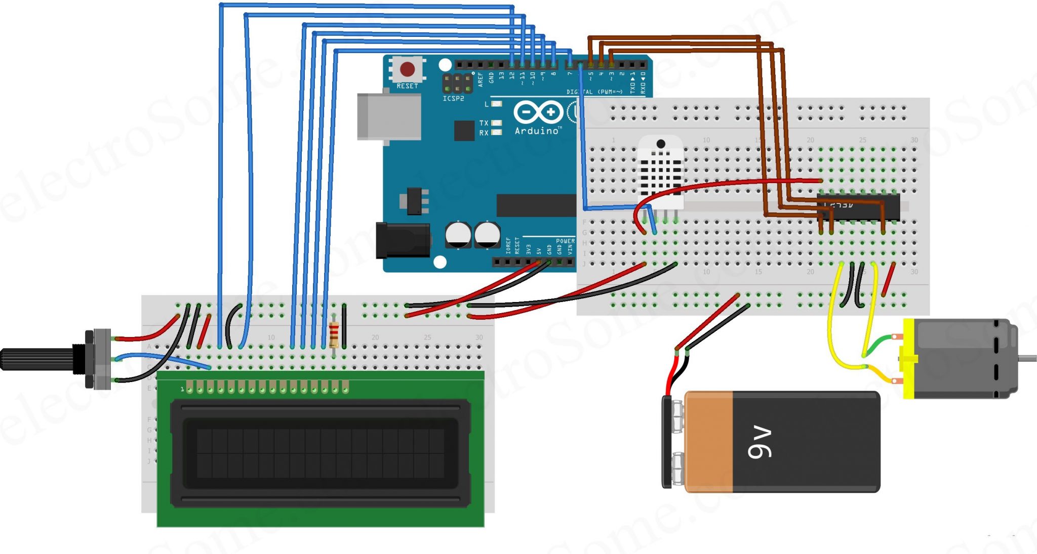
This application is simple just by using temperature sensor LM35 with an arduino kit to control a fan and change its speed with respect to the temperature read by the micro-controller which in this case is the arduino kit. The temperature sensor LM35 is connected with the arduino with an analog input pin A0 (the temperature is an analog signal), while the fan is connected with a PWM (Pulse Width Modulation) pin 6 which controls the speed of the fan with respect to the output temperature using a function map in the arduino IDE.
The Components needed: 1. Temperature Sensor LM35 3. 1K Resistor 4. Diode 1N4007 5.
This application is simple just by using temperature sensor LM35 with an arduino kit to control a fan and change its speed with respect to the temperature read by the micro-controller which in this case is the arduino kit.
Dc Motor or a simple DC fan 6. NPN transistor BC547 7. A voltage source with 12Volts 8. Hook up wires 9.
Optional: voltage source socket. Schematic •using the NPN transistor BC547 here as a buffer to isolate the first circuit which is the connection to the arduino and the other one with the fan. •using an inverted PN-junction parallel to the fan to prevent moving current in the opposite direction and make damage to the arduino kit. •using a PWM pin is to modulate the signal given to the fan with respect to the read temperature and by using the map function to control the fan speed. •it is important to put in consideration that the input voltage for the temp sensor is 5v from the arduino itself, and the 12volt voltage given to the motor or fan must be from an external voltage source, in this case we collect all the GND together weather the GND of the arduino and the external voltage source. You might've had this question answered, but for others who are curious - the fan is an inductive load, and the diode therefore serves as a 'flyback diode'. Technically, the fan's motor develops a magnetic field in order to spin.
When the fan suddenly loses power (when you turn it off at the switch), it tries to 'feed itself' using the motor's collapsing magnetic field as its source, instead of the original source - which is now missing. Depending on the magnitude of this field, the inductor creates a negaitve potential where it was once positive, and the inductive load tries to essentially 'force' the voltage across the power switch, creating an arc. This is dangerous for the circuit. A diode is therefore placed across the motor such that the intended source won't bypass the fan when operating, and the inductor will 'power itself down' PROPERLY (until it dies) when the fan is turned off. Hope this helps:).
Slide2: / Arduino based Automatic Temperature Controlled Fan Speed Regulator Introduction This practical temperature controller controls the temperature of any device according to its requirement for any industrial application, it also has a feature of remote speed control. The LM-35 Analog Temperature device is interfaced to analog pin of Arduino board, where it has built in ADC which converts these analog reading and displays it on a LCD, which indicate the temperature of the device. User-defined temperature settings can be done using push buttons provided through Arduino board.
Slide16: / LM 35 Temperature Sensor Arduino based Automatic Temperature Controlled Fan Speed Regulator LM35 are used to sense the heat and an IC ADC0808 is used to convert the data into digital. LM35 digital sensor has got 3 pin’s i.e., VCC, GND and output pin’s when LM35 is heated the voltage at output pin increases. It is connected to the analog to digital convertor IC (ADC). Periya puranam story in tamil pdf. The LM35 series are precision integrated-circuit temperature sensors, whose output voltage is linearly proportional to the Celsius (Centigrade) temperature. Slide22: / Operation of Motor Driver Arduino based Automatic Temperature Controlled Fan Speed Regulator If enable 1 and pin number 2 are high leaving pin number 7 as low then the motor rotates in forward direction. If enable 2 and pin number 10 are high leaving pin number 15 as low then the motor rotates in forward direction. If enable 1 and pin number 2 are low leaving pin number 7 as high then the motor rotates in reverse direction.

If enable 2 and pin number 15 are high leaving pin number 10 as low then the motor rotates in forward direction. Slide24: / Working Principle Arduino based Automatic Temperature Controlled Fan Speed Regulator User-defined temperature settings can be done using push buttons provided through Arduino board. Maximum and minimum settings are used for allowing any necessary hysteresis. Few push buttons are used to set the temperature by INC, for increase and DEC for decrease settings. As soon the max and min temperatures are set then the Arduino program generates PWM output on the corresponding digital output according to the measured temperature.